In Part 1 of this Hydroponics Equipment article we looked at how to store nutrient and deliver it to plants in the grow channels.
In Part 2 we look at how to build hydroponic grow channels for growing tomatoes and cucumbers using a hydroponic drip system. Let’s take a look at the overall design first. I am indebted here to the work of Howard M. Resh and his book Hydroponic Tomatoes for the Home Gardener for the basic design idea.

Rockwool slab culture – hydroponic drip system design
The hydroponic grow channels are shown here with 1 metre Grodan Rockwool slabs and support strings for tomato plants in place. The irrigation system is not shown (see part 1 for details). The total length of the grow channel here is 3.9m but other lengths can be produced depending on the space you have available. Generally grow channels are positioned north to south rather than east to west so that may influence the specific length in your polytunnel. The design length was also determined by the rockwool slab size – it allows for 3 x 1.2m slabs with 0.25m of overhang for a nutrient drain.
The hydroponic grow channel is made from:
- 2 x timber constructed grow channels of 1.95m length each (to make 3.9m full length)
- 3 x support trestles of reducing height to create a gradient of 5.5cm in about 2m i.e. a 2.75% gradient.
- pond liner

Hydroponic grow channel section
Building the grow channels
The grow channel needs to be circa 220mm wide to accommodate the width of the rockwool slabs and to allow nutrient to flow round them. In theory this would involve a 220mm wide by 18mm thick by 3.9 metre length piece of timber. For ease of transport and cost, 2.4m length tongue and groove floorboard of 121 x 18mm can be used. The timber is sawn to 1.95m length and then one of the tongues sawn off with a table saw (so the edge of the wood is flat). The unused groove is also sawn off. The two pieces can then be pushed together to produce a single piece 220mm in width. The offcuts from the timber are used as mending plates to join the 220mm piece firmly together. Lengths of 18 x 44mm timber are then screwed to form the sides of the channel. 18mm x 44mm timber is also screwed to one end of the channel to close it off. The other end is left open. The whole unit can then be painted using an undercoat and gloss coat to allow cleaning and washing down. Whilst the channel pieces are drying, the wood supports can be started.
Building the support trestles
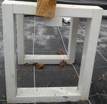
Hydroponic grow channel support trestles – Two rectangles joined with a cross piece
Various designs of trestle were considered but in the end simple wooden rectangles were constructed which were then joined together in pairs with a cross piece on which the grow channel sits. A job lot of 38mm x 63mm x 2.4m timber was on special offer locally so this was used, although other sizes can be used.
To build a pair of the the highest rectangles for the trestle requires:
- 4 x 0.44m length timber
- 4 x 0.29m length timber
- 1 x 0.42m length timber (cross piece to join the two rectangles)
- 20 x 70mm woodscrew
For the middle trestle replace the 0.44mm length with 0.385m. Likewise for the lowest trestle use 0.33m lengths.
Again these need to be painted with gloss paint so they can be easily cleaned.
Assembling the channel
Lay the trestles out, in their desired position in the polytunnel, in decreasing height order with the lowest one near to the drain you are going to use for recycling the nutrient. My drain runs down the outside of the polytunnel so that’s where the lowest trestle is positioned. They need to be spaced pretty much equally apart – the middle trestle is going to support both channels so it needs to be dead centre. The lowest trestle needs to be offset about 0.3m away from the end of the channel to allow a slight overhang to put the nutrient drain hole that needs to be installed. Lay the channel on the cross piece of the trestles, so that the two channel pieces butt up against each other with their open ends together.
The channel now needs to be bolted to the trestles. For this you will need:
- 8mm wood drill
- 8 x M8 x 65mm bolts and nuts
Drill two holes through the channel and into the cross support. The holes need to be about 75mm left and right of the centre line of the channel. Make sure the bolt head is at the top and the nuts are tightened from underneath the cross support piece. The bolt head is smoother and will not pierce the pond liner that will cover it. It will also allow you to remove the trestles from the channel without having to remove the pond liner in the future.
So we now have a grow channel which is closed at both ends.
Fitting the pond liner
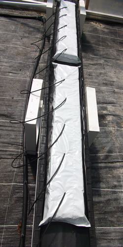
Hydroponic grow channel with rockwool slabs
Lay the 4m length of pond liner along the top of the channel edge and staple down one side with staples every 40-50mm (see cross section diagram above). Enough pond liner should be left to allow the closed top edge to be stapled next. When one side and the top is fixed then push the pond liner down into the channel so that it settle flat into the corners of the channel. You can then staple the other side and the bottom closed edge. Once the liner has been fully stapled you can then trim any material that hangs over any of the edges of the channel. Black gaffer tape can then be used over the staples and the exposed side of the channel.
The final task is to allow for a nutrient drain. Drill a hole for a conventional sink waste, using a holesaw, at the very bottom of the channel. Then install the sink waste suitable for 40mm waste pipe.
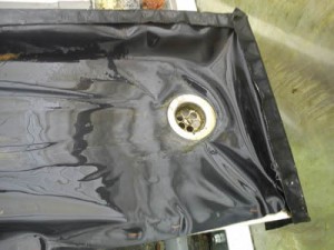
Nutrient drain in hydroponic grow channel
In Part 3 of Hydroponics Equipment Needed To Set Up A Hydroponic Drip System we will look at the equipment needed for recycling and filtering nutrient as part of our closed hydroponic system.
Back to Part 1
Leave a Reply